
Making a movie from an AMBER trajectory using VMD
You want to generate a nice movie from your trajectory data.
Movies are always useful to show a simulation. In this tutorial we are going to use the Visual Molecular Dynamics ‘VMD’ visualizer from developed at the University of Illinois at Urbana-Champaign. For this tutorial we are going to use a trajectory of a protein receptor that has a bound ligand in the active site. The topology file is vph.prmtop and the trajectory file is vph.nc. This tutorial has been prepared in an PC computer running the Linux Ubuntu operating system with VMD version 1.9.3.
Start VMD.
With the topology and the trajectory file downloaded, go to:
File -> New Molecule
Load the vph.prmtop topology first! Select the file and click the Load button.
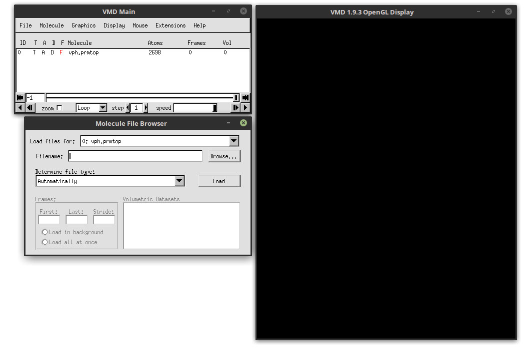
Now click the Browse button and select the trajectory file vph.nc. Make sure that the ‘Load files for:’ has the vph.prmtop topology selected. This means that the trajectory file that we are going to load is going to be linked with the topology file, hence the importance to read the prmtop file before the trajectory file.

Click the load button to load the trajectory file. Each of the frames will load into VMD. You should see the protein in the main VMD window (the windows with the name ‘VMD 1.9.3 OpenGL Display’). The colors could be somewhat different.
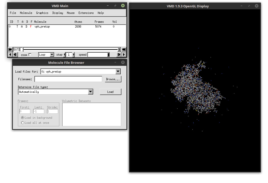
Now that we have loaded the topology and the 5074 frames, we can edit how the system will look. Close the ‘Molecule File Browser’ and go to:
Graphics -> Representations...
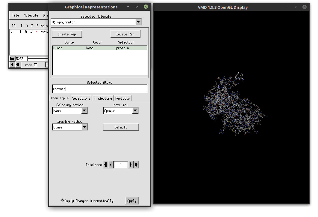
This will open the ‘Graphical Representations’ window.
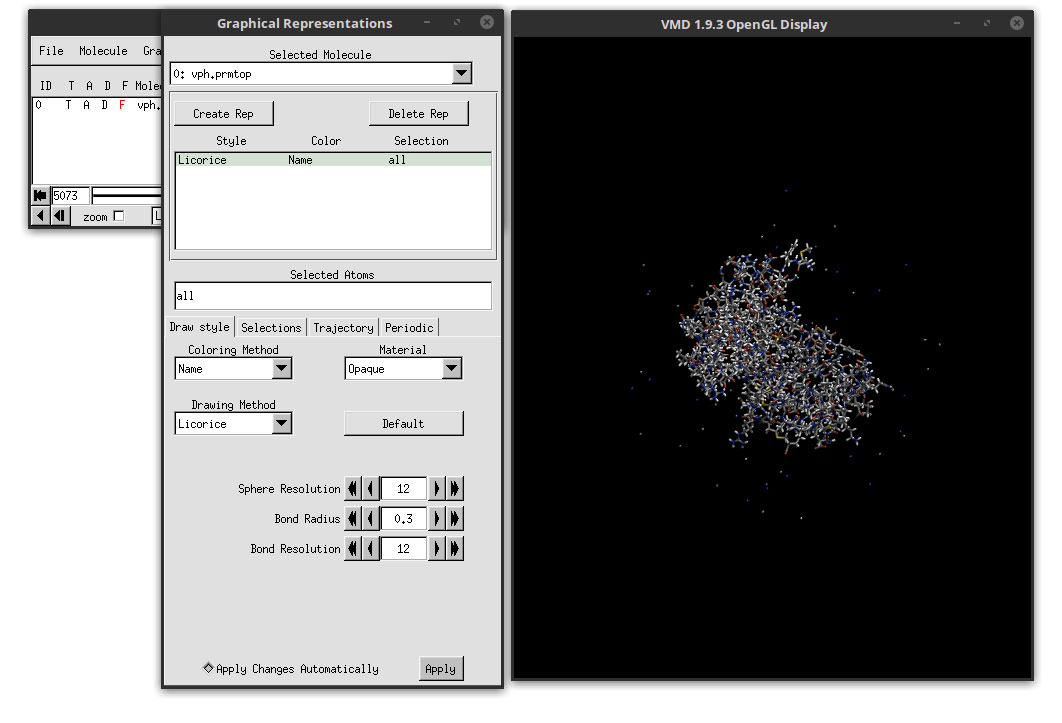
In this window we can adjust the representations of the protein, the ligand and the ions if needed. We will use different methods of visual representation for the protein and the ligand. To do this, we have to select the protein only. In the ‘Selected Atoms’ field, delete the word ‘all’ write the word protein. This will select only the atoms that are included in the protein.
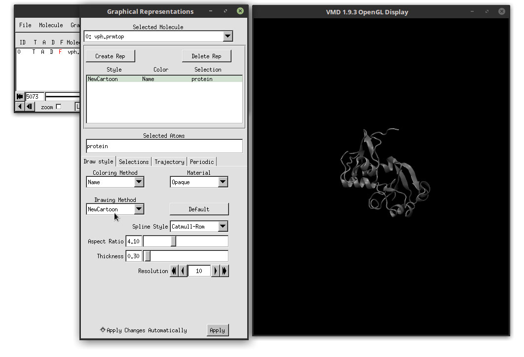
Now let us choose a better representation for the protein. In the ‘Drawing Method’ menu, click and select: NewCartoon
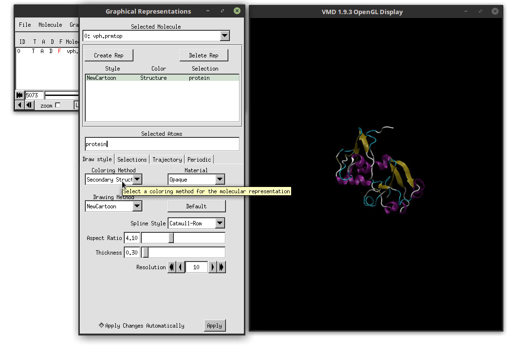
This will change the representation of the protein for a more easier visualization were alpha helices and beta sheets are easier to distinguish. Let us change the color to enhance these features. In the ‘Coloring Method’ drop-down menu, select: Secondary Structure
With this coloring method, each secondary structure will be colored by a different color, which highlights each region accordingly. In order to enhance our movie, we are going to change the Material that we are using to add color to the structure. In the Material drop-down menu, select: AOEdgy
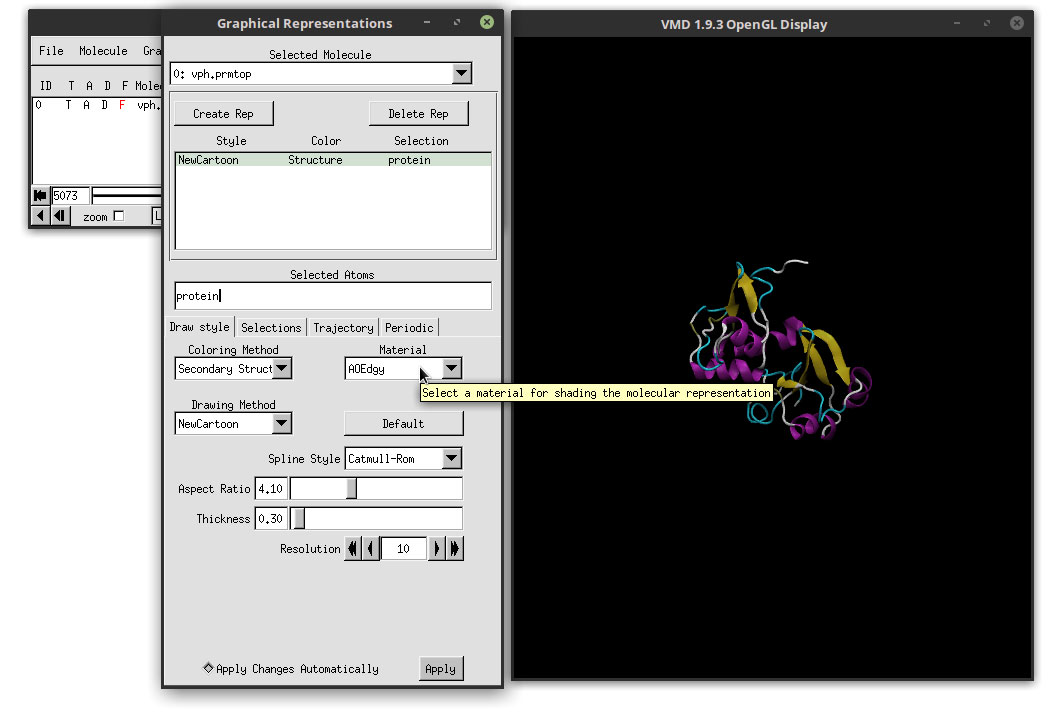
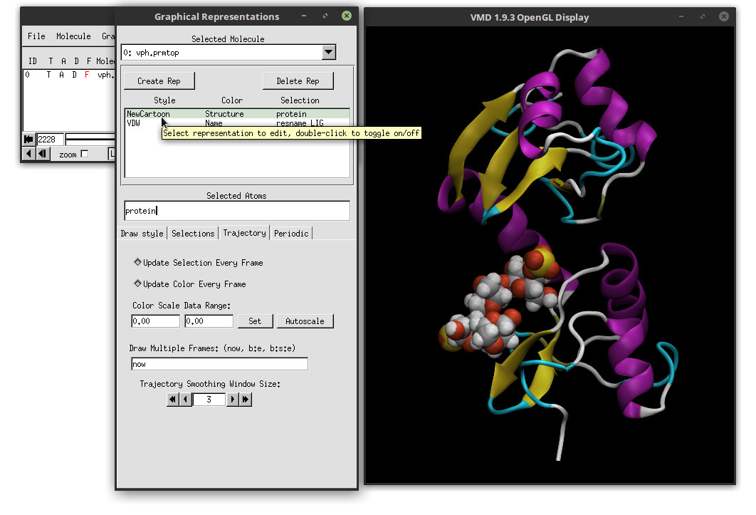
This material makes the overall representation more bright and also will make use of a special render engine available in VMD as we will see in the next steps. But for now, let us focus on the ligand. To select the ligand and change the representation, we need to add a new representation. Click on the ‘Create Rep’ button in the Graphical Representations window.
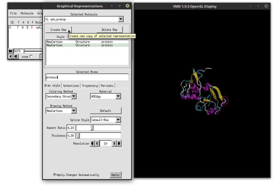
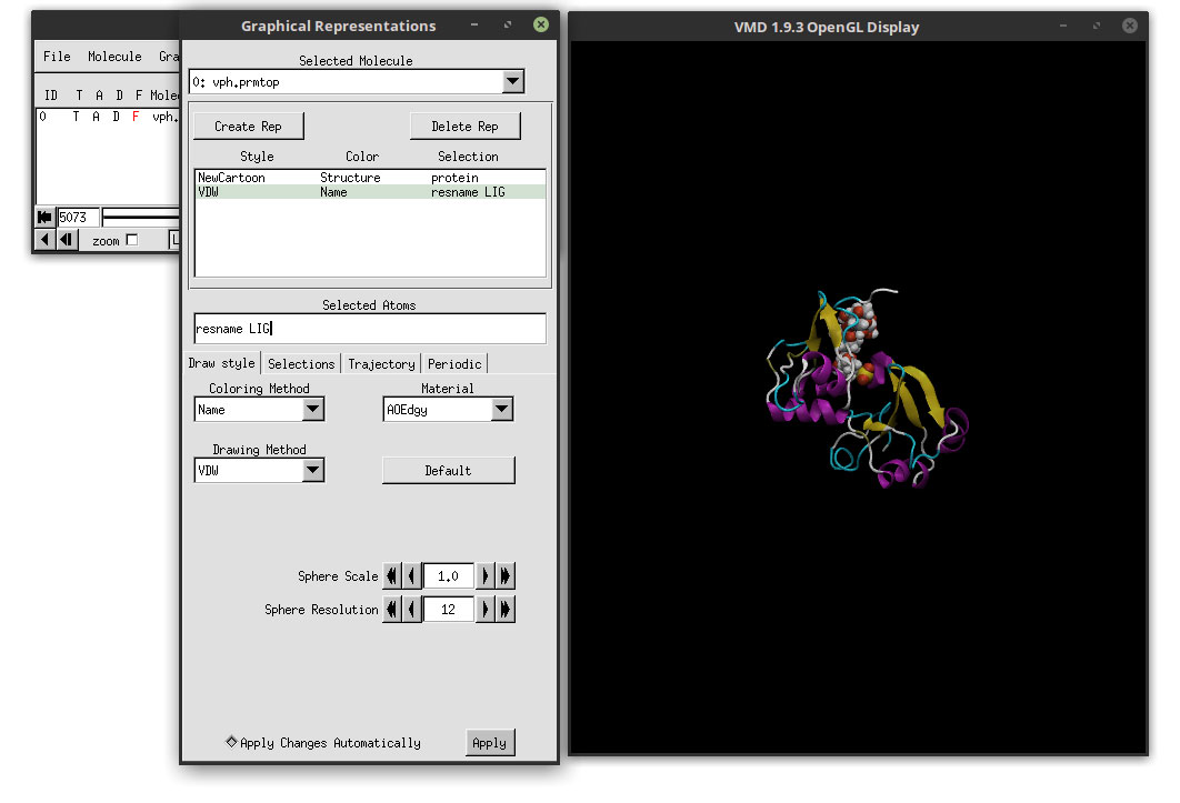
This will copy the current representation that we have, that we will use as a template for the ligand. In the ‘Selected Atoms’ field, delete ‘protein’ and type: resname LIG
This will select all residues that have the name ‘LIG’. In our case, we only have one residue with that name, which will appear in VMD’s main window. Select Name as the Coloring Method and VDW as the Drawing Method. The result is:
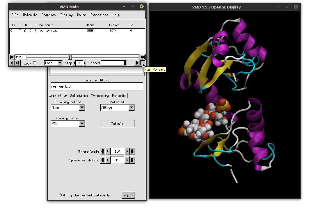
We can clearly see the ligand docked in the active site of the protein. Since we made a copy of the protein’s representation, the Material is still showing the AOEdgy material, which is what we want. We can visualize the movie with this new representations of the ligand and the protein by clicking on the play button in the ‘VMD Main’ window, and we can use the mouse to adjust the perspective of our system. Click on the OpenGL Display and use the mouse to rotate the 3D perspective of our system. You can switch between 3D rotation mode by hitting the ‘r’ letter in the keyboard. If you type the ‘s’ letter, you can scale (zoom in and zoom out) and with the ‘t’ you can translate the system. To go back to 3D rotation, hit the ‘r’ again.
The movie is starting to look better. If we hit play to preview the movie, we notice that the animation is not smooth and that is very ‘bumpy’. This is because of the frequency of saving trajectory data when we are running the simulations. Saving too often does make the animations smoother, but the trajectory files are extremely big and not very convenient. To smooth the animation, we can use the ‘Trajectory Smoothing’ option. Click on the ‘Trajectory’ tab and apply a ‘Trajectory Smoothing Window Size:’ of 3.
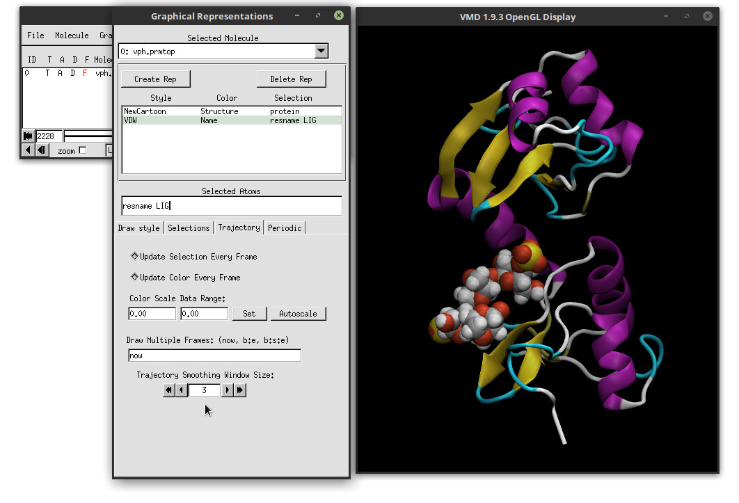
We have to do this for the ligand and for the protein. We can change between each by clicking in the Graphical representations list of molecules.
Hit the play button and the animation will now run quite smooth. Our molecules are ready, but we need to adjust a couple of more option before rendering our movie. Lets change the background to white, which will enhance the shadows of the molecule and helps in the depth perception. In the ‘VMD Main’ window, go to:
Graphics -> Colors...
In the Categories, select Display. In the Names, select Background and use the color sliders to change to white.
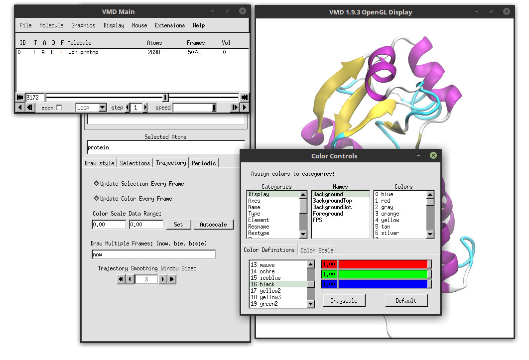
Close the ‘Color Controls’ windows and go to:
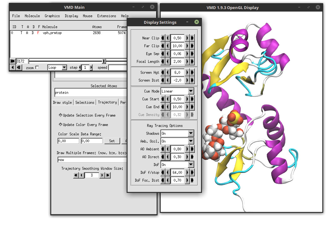
Display -> Display Settings…
Select in the ‘Ray tracing Options’ Shadows On, Amb. Occl. On and DoF On Select the Cue Mode Linear. All of these options will turn on the shadows, the ambien occlusion and the depth of field which really enhances the look and feel of the final video.
With all of these parameters, we are ready to generate the movie. Close the ‘Display Settings’ and ‘Graphical Representations’ windows. Go to:
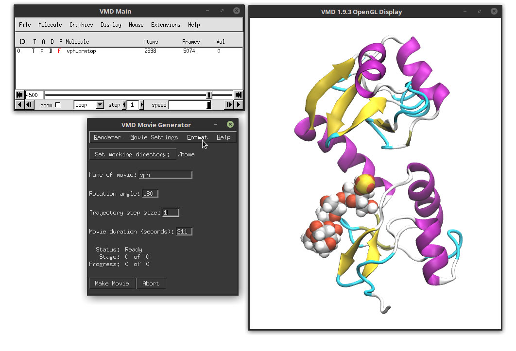
Extensions -> Visualization -> VMD Movie Generator
We will select a path in our computer to save the movie using the ‘Set working directory’. In the Name of the movie, write the name of the output file. In the Renderer we will chose 'Internal Tachyon', Movie settings: 'Trajectory', Format ‘MPEG-2, NTSC DVD’ and we click on the Make Movie. These are options that most of the time work and that are a good balance between quality and time. Some systems will need to install external libraries and programs (like the ffmpeg program). In some cases it is just easier to render a series of image files that later we can convert to a movie file. This also generates the maximum quality but can take considerable time.
For this example, and to make it as universal as possible regardless of the system, we will generate a series of image files in the JPEG format that we can later stitch together in a movie file. In order to do this, we need to select:
Format -> JPEG frames (ImageMagick)
and then click the ‘Make Movie’ This will generate one image file for each frame of our simulation and each frame will be saved in the working directory.
- VERY IMPORTANT – The generated files will have the same size as the Display window (the OpenGL window). Maximize the size of the window to make sure we get the correct window proportion and the maximum resolution.
After the render is over, we can use the command:
convert -delay 6 -quality 95 final*jpg movie.mp4
To convert the images to a movie, which look like this (if no movie shows, you can download the movie file here):